… the OpenEVSE can measure both single phase and 3 phase charging, without any need for additional current sensors or changes to the firmware.
With it’s built in features and open nature, the OpenEVSE is a very powerful piece of equipment for charging an electric vehicle. But with a few modifications, such as a 4 pole contactor and some extra wires, it can become even more powerful in another sense—in fact, 3 times as powerful—by delivering 3 phase power.
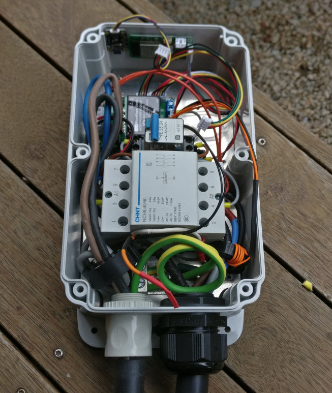
However, to accurately measure charging current—essential for solar divert and keeping an accurate record of the energy delivered by the charging station—a little more is required.
Measuring Single Phase Current
To measure and display charge energy transferred into the vehicle, the OpenEVSE measures the AC RMS current, then multiplies this by AC RMS voltage, to get apparent power.
This power measurement, assumed to be close enough to real power, is integrated over time to calculate total energy (in kWh), for both the charging session and the station’s lifetime.
The current is measured using the current sensing coil, with one conductor of the single phase supply (typically the active wire) passing through the coil.
The voltage reading that’s required isn’t actually measured by the OpenEVSE, since it lacks the hardware for such a measurement. The value used for the calculation can either be set statically in the OpenEVSE settings, or read from another source over MQTT.
The power calculation method used by the OpenEVSE differs from that used by a utility grade meter, in that a utility meter multiplies the actual DC voltage and DC current in real time at every point in the AC cycle, thus the utility meter can take into account reactive power and harmonics that would otherwise cause a calculated value higher than the real power.
However, this is not a significant problem with the OpenEVSE, since the charger in an electric vehicle typically has a power factor close to one. So multiplying RMS current and voltage yields a measurement accurate enough for most situations.
Problem with 3 Phase
On the surface, to measure 3 phase current, it might seem possible to pass all 3 active conductors through the current sensing coil. However, if this was done, the currents in the 3 wires won’t add together—they instead cancel out. If the 3 current are equal, these currents will cancel out exactly and the sensing coil will measure zero.
With a small change to the OpenEVSE firmware, it is possible to measure only one active conductor and get an accurate measurement by allowing the firmware to multiply the measured value by 3.
However, this solution will only work for 3 phase vehicles. If a single phase vehicle uses an OpenEVSE with this firmware modification, the calculated charging power is only 1/3 of the correct value.
First Solution
Assuming a power factor of 1 (no reactive power or harmonics), and assuming that the load through the sensing coil will always be either (1) single phase using L1 and neutral only, or (2), balanced 3 phase, it is possible to measure the current using no additional current sensing hardware.
As mentioned before, three equal AC currents, flowing in the same direction but 120 degrees out of phase as used in 3 phase electricity distribution, will cancel each other out. In this case, half of current in L1 is cancelled by L2, and the other half is cancelled by L3.
But if L2 and L3 are physically reversed—the wires passing in the opposite direction to L1, the currents will add. Half the value of L1 is added by L2, and half the value of L1 is added by L3. Hence, twice the current is registered compared with measuring L1 alone.
Taking it a step further, if L2 and L3 pass through the current sensing coil twice in reverse, the contribution from L2 and L3 is doubled, and 3 times the current passing through L1 is measured in the coil. Hence, the measurement of three balanced phase currents has been achieved.
| L1 | L2 | L3 | Sum | |
|---|---|---|---|---|
| Vector Current (A) | 16 | -8+13.856i | -8-13.856i | 0 |
| Measurement Multiplier | 1 | -2 | -2 | |
| Measured Current (A) | 16 | 16-27.713i | 16+27.713i | 48 |
According to the Type 2 standard, vehicles that only charge using one phase always charge from L1. In this case, only the current from L1 is measured, so the measurement is still correct.
Second Solution
In the solution above, L1 passes through the coil once, L2 twice, and L3 twice. This might work in theory, but squeezing 5 conductors sized for 32 amps through the OpenEVSE current sensing coil could be challenging.
It can also be shown that passing L1 through once forward, L2 also once forward, and L3 twice backwards, has the same result. This requires only 4 conductors to pass through the coil, rather than 5.
| L1 | L2 | L3 | Sum | |
|---|---|---|---|---|
| Vector Current (A) | 16 | -8+13.856i | -8-13.856i | 0 |
| Measurement Multiplier | 1 | 1 | -2 | |
| Measured Current (A) | 16 | -8+13.856i | 16+27.713i | 48 |
Again, in the case where only L1 is used for single phase vehicle charging, this solution still works. In fact, if L2 was used for single phase charging, this solution would also work.
I can confirm that the 4x 6mm2 flexible conductors are able to fit through the current sensing coil provided with the OpenEVSE using the second method.
Mathematical Test
To test any other situation, download the spreadsheet below and experiment with different phase currents that could be passed through the coil. The spreadsheet uses complex numbers to represent the currents in vector form.
Physical Test 1
To confirm the theory, I connected a dummy resistive load to a separated extra low voltage (12/21 V), 3 phase power supply.
It should be noted that there was no neutral conductor involved in this test. However, as we are ignoring unbalanced loads and harmonics, there should be no neutral current anyway.
The following table shows the currents shown on each wire, and how the wires were passed through the AC clamp current meter for each measurement.
| L1 | L2 | L3 | Sum | |
|---|---|---|---|---|
| Photo | 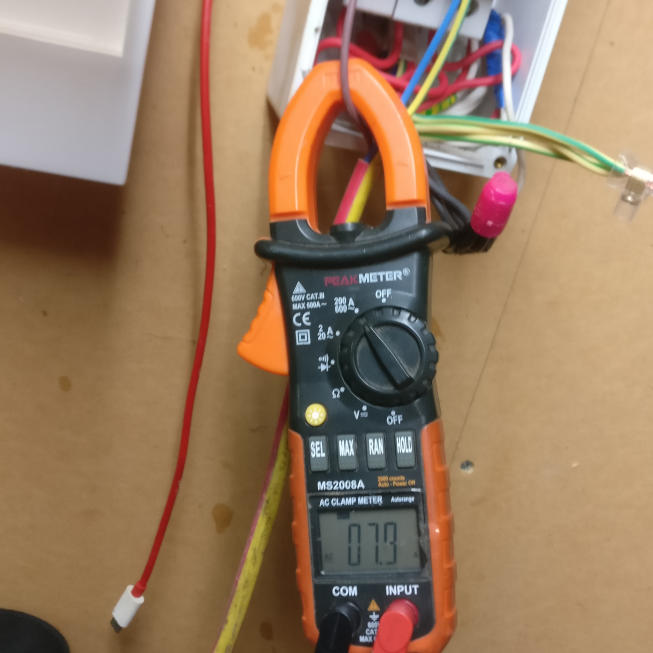 | 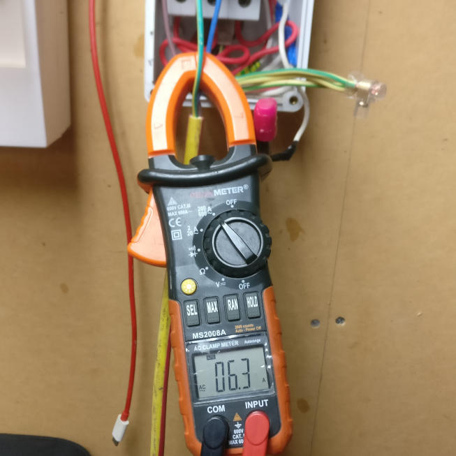 | 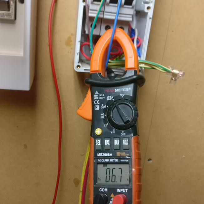 | 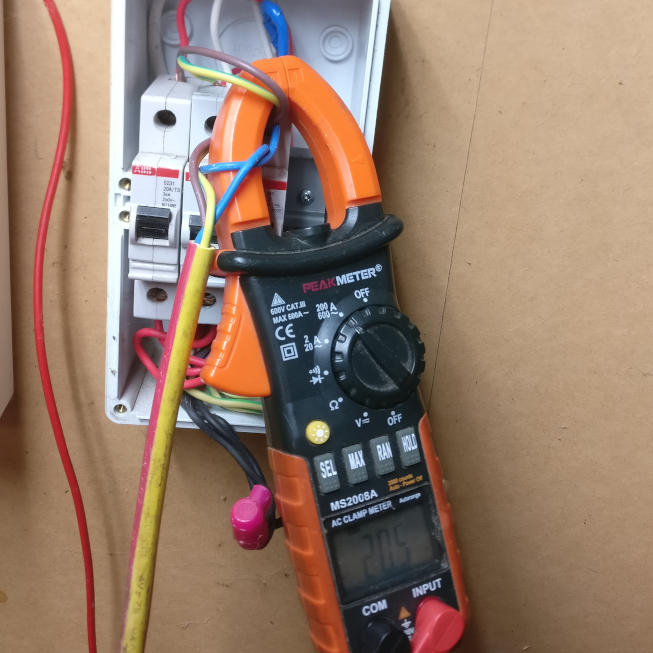 |
| Actual Measurement | 7.9 | 6.3 | 6.7 | 20.5 |
| Predicted Measurement | 20.547 |
Experiment Results
This result proves that the solution works for both single phase and balanced three phase measurements.
Physical Test 2
Of course no test compares to actually wiring the OpenEVSE this way and charging a 3 phase capable vehicle.
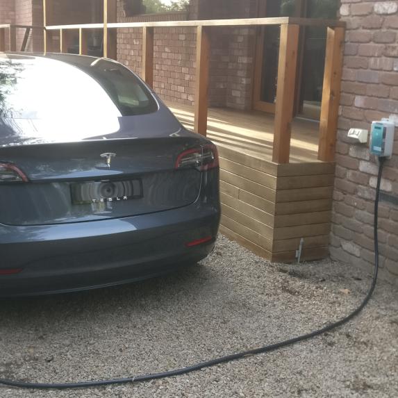
The Tesla Model 3 can charge at 16 A per phase, or 48 A total, for a total of about 11.5 kW. This is at 230/400 V, as used in Australia, Europe and many other places.
And just as hoped, the current seen by the OpenEVSE is the scalar sum of all 3 phases!
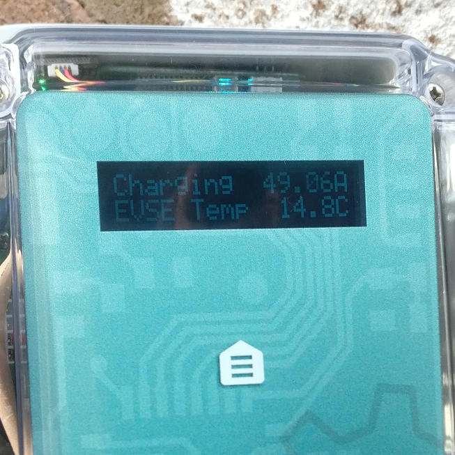
Overcurrent Error
Unfortunately, there is still one problem. The OpenEVSE firmware, taking safety more seriously than other charging stations, will stop charging if the current sensed in the sensor exceeds what the station tells the vehicle it can take.
In the case with this Tesla, if the station is set to deliver 48 A or more, it all works as intended, since the car won’t take any more than 48 A total.
However, if the charge rate is reduced to anything less, say 40 A, the car will continue to draw 16 A per phase, because the station tells it 40 A is available. Therefore, 48 A is still flowing through the coil, and an error is generated.
This can be circumvented with a modification to the firmware, by commenting out the OVERCURRENT_THRESHOLD declaration in the openevse.h source header file, compiling, then uploading the firmware with the OpenEVSE programmer or similar device.
I’m choosing not to undertake this right now, since limiting charging current isn’t so important for visiting 3 phase vehicles, only for my own single phase Renault Kangoo.
Conclusion
These methods show that the OpenEVSE can measure both single phase and 3 phase charging, without any need for additional current sensors or changes to the firmware. Still, to maintain the ability to limit the charging power of a 3 phase vehicle, a minor change to the firmware is still required.
